Project
An AeroPress that presses itself
coffee-bot grinds beans, heats and doses water, blooms, brews, presses the plunger, ejects the puck, and cleans itself — driven by an ESP32-S3 running ESPHome, with a monochrome front panel for control and Home Assistant for brew history and graphs. Built in nine strictly-gated phases: no phase starts until the previous one survives its endurance test.
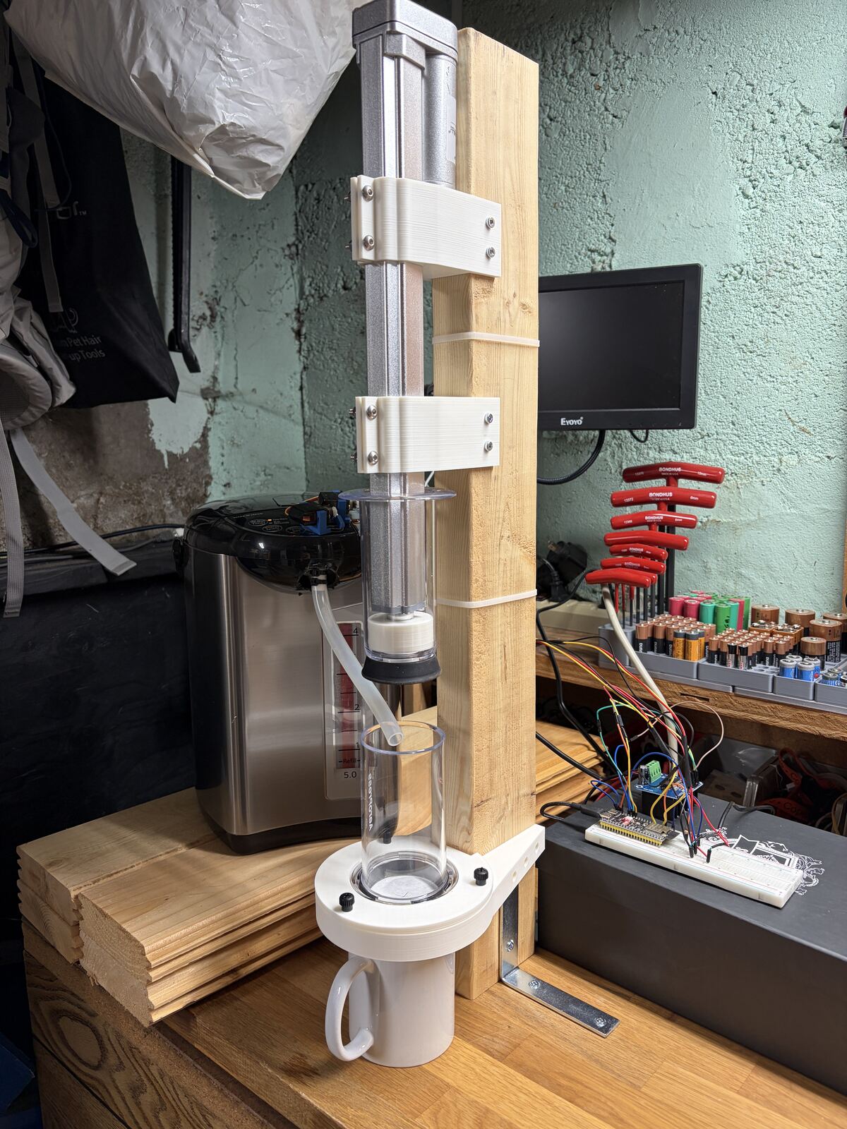
Right now
Phase progress
Fill = steps resolved (done or deliberately dropped). Click a phase to open it.
System architecture
The ESP32-S3 is the whole machine — state machine, all I/O, safety interlocks, recipe presets, and the front panel. Home Assistant (optional, any always-on box) connects over the native API for brew history, graphs, and dashboards with zero custom code; the machine is fully functional without it. The originally planned Raspberry Pi + custom web app was dropped 2026-08-16 — deterministic, fail-safe control was always on the microcontroller, and HA covers everything the Pi was for.
Major decisions the load-bearing ones
UL-listed appliance, not a gutted kettle
Phase 1 heat comes from a stock Tiger PDU-A50U dispenser. Servos press its buttons from outside — zero electrical contact, zero teardown, the appliance keeps its own thermal safety stack. Why →
Stationary chamber, one axis
A 12″ actuator presses straight down into a fixed AeroPress. The rotating two-station plate was rejected: a motor, indexing, and a thrust bearing bought nothing a cleaning cycle can't. Why →
±15 mL accepted for v1
Open-loop timed pours can't beat pump spin-up variance. ~6% water error is imperceptible in an AeroPress; ±5 mL waits for the load-cell closed loop. Why →
No stirring, by design
Bloom phase + pulsed dispense + an offset pour swirl the grounds for free. Software and geometry replace an entire mechanism. Why →
Temp probe dropped for v1
The Tiger holds its own setpoint 24/7; nothing in the dispense path needs an independent reading. The DS18B20 was a nicety, not a control or safety input. Why →
Never 3D-printed in the wet path
FDM layer lines trap bacteria and coffee oils. Stainless, glass, silicone, or the AeroPress's own polypropylene touch water — PETG is structure only. Why →
Build log key dates
- 2026-05-27
Phase 1 pivot: Tiger PDU-A50U hot-water dispenser replaces the gutted-kettle PID design — UL-listed appliance takes over all thermal regulation and mains risk.
- 2026-05-31
Servo interface chosen over optocoupler teardown — fully reversible, warranty intact. Slip-over 10 mm silicone plumbing replaces the push-in plan.
- 2026-06-03
Servos bench-validated: both MG90S units press the Tiger's buttons with torque to spare. Bracket modeling begins in Fusion 360; stock horns with arc-tuned geometry.
- 2026-06-05
Firmware flashed, live on WiFi. Servos calibrated in-place (unlock 0.55 / dispense 0.45). Dead-time dispense model fitted: 32.0 mL/s + 1750 ms. Auto-relock measured ~10 s.
- 2026-06-08
Two v1 calls: DS18B20 temperature monitoring dropped (appliance self-regulates); ±15 mL open-loop tolerance accepted, ±5 mL deferred to a load-cell closed loop.
- 2026-06-09
Endurance harness written (
scripts/endurance_run.sh) and smoke-tested — cycle 1 fired clean over REST. - 2026-06-10
Unlock press regressed — second geometry walk in a week; printed clamp-over horn extension under consideration. Site launched at coffeebot.alexmeub.com.
- 2026-06-11
Phase 1 exit gate passed: 50/50 endurance cycles, zero failures, zero interventions. Same day: unlock press re-landed at 0.53; recirc back-pressure leak at the spout gap found and sealed.
- 2026-06-13
Phase 1 fully closed; Phase 2 kicked off. Flow sweep found ~65 mL tank-level drift → fix with app-side tank-level compensation + fill bar (and/or the load cell). Drive-chain parts ordered.
- 2026-06-18
Phase 2 step 1 done: actuator extends/retracts full-stroke under ESP32 control via the BTS7960, Stop halts instantly. Firmware flashed (ESPHome 2026.6.1, OTA).
- 2026-06-23
Phase 2 step 3 done: plunger aligned, press pushes through the chamber with no binding. MVP goes open-loop (limit switches deferred).
- 2026-06-24
Press cycle calibrated dry; brew/clean sequence drafted. Open-loop timed press scripts + bench buttons.
- 2026-06-25
First real brew works. Fast seal plunge + ~5 mm backoff pulls a vacuum that holds the water through a 90 s steep; slow extract presses it through; puck ejects by contact (pneumatic eject didn't pan out).
- 2026-08-06
Phase 3 kicked off in parallel: Baratza Encore replaces the gutted-blade-grinder plan — appliance untouched, mains switched by an enclosed relay box. Restart-on-power-apply verified; timed-dose firmware flashed.
- 2026-08-14
Grinder power control proven: relay wired, full bring-up passed — boot-safe, 75 s watchdog, mid-dose abort. Grounds drawer printed; spout → air gap → catch-funnel delivery design drawn.
- 2026-08-16
Architecture simplified: Raspberry Pi + custom web app dropped. Home Assistant takes history/graphs over the native API; Phase 6 re-scoped to firmware (recipe presets, tank compensation) + a monochrome front panel (SSD1322 OLED + Brew/Clean buttons).
- 2026-08-16
Dose calibrated by weight: 1.50 g/s at grind setting 14 with RDT —
grind_dur_ms10667 ms, validation dose 16.0 g dead-on, 0.0 g spread on every calibration pair. Static beaten by adopting RDT (spritz the hopper beans) as part of the routine. - 2026-08-17
Spout v2 validated (Ø26 exit, steady stream) — delivered rate 1.40 g/s,
grind_dur_ms11400. The lesson: over-spritzing cakes the path — RDT is 1–2 mists per fill, only. - 2026-08-20
Rim brim built + clearance test passed. Both inputs plumbed into one printed brim (grounds socket + water port, opposite sides, 60°); the plunger passes both nozzles and the inner ring with zero contact. Press-safe — the "remove the hose before pressing" era is over.
- 2026-08-20
THE MACHINE MADE COFFEE. First full hands-free brew cycle — grind, pour, vacuum steep, extract, mug — one unattended chain. Slightly weak but good. New issue at eject: the plunger's Ø84 lip grazes the port towers at deep press → fix is trimming the lip into the seal's proven-clear column.
- next session
Trim the plunger lip + full-depth clearance re-check · re-tune the contact-eject distance · finer grind (setting 13) for the next cup · 20-dose repeatability gate · Phase 2: 50-cycle endurance gate.
The discipline
Working log
Build log
Chronological record of the build — progress, issues, and the calls made along the way. Newest first. The overview timeline shows highlights; this is the full story.
-
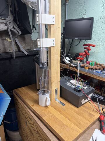
The rig graduated from "parts arranged on a bench" to an actual machine: a butcher-block base with a 15 in shelf wrapping the main 2×4 actuator column, with the Encore and the Tiger now sitting securely on the shelf instead of loose alongside. The plunger lip is trimmed flush to the barrel, closing the issue that aborted the first brew's eject — the Ø84 second keep-out is gone and the plunger is a plain ≤Ø64 column for its whole length. Two things are still owed before any powered press: the full-depth clearance descent (the 08-20 test only went just past the brim ring) and the contact-eject re-tune.
The extra height reopens the grounds path. The as-built brim enters at 60°, and the working theory for grounds escaping the chamber was that they exit with too much lateral speed, cross the bore, and ricochet off the far wall. Counterintuitively the fix is a shallower entry (~45°): drop height is fixed by the shelf, so a shallower chute is a longer one, friction eats more energy, and grounds arrive slower and land instead of bouncing. The floor is coffee's friction angle — below ~40° it stops sliding reliably, more so RDT-damp. A polished stainless tube is the likely material: lower wall friction than PETG, no static once bonded to the frame (the old "grounded stainless liner" idea, promoted to being the whole tube), and genuinely cleanable. Flexible food-grade hose was considered and rejected — any unsupported span sags into a valley that retains a variable 0.5–1 g, and silicone is both tacky and strongly static-generating, the worst surface for the problem RDT exists to fight.
On diameter, the arithmetic says smaller isn't the lever. 16 g at 1.40 g/s is only ~4 mL/s of volumetric flow, so the tube runs under 5 % full at any bore in contention — the grounds slide as a thin ribbon on the bottom wall, and bore size barely changes the stream's shape. It changes clog risk, and bridging risk compounds with shallow angle, so shallow + narrow + damp is the one combination to avoid. Ø26 is the proven number; the target is ~Ø23–26 ID (1 in OD × 0.049 in wall stainless lands at ~Ø23), and the collimating gets done at the exit — last section close to the rim, aimed at the near half of the bore — rather than by squeezing the whole run. A low shroud outside the Ø66 keep-out, now affordable with the lip trimmed, catches whatever still bounces. The reference build that prompted the shallow-angle idea turns out to use a wide, flat ~20–25° ramp into a generous collar — containment at the receiving end, not a narrow stream. It's written up in full on the new prior art page, which is worth reading for a second reason: their actuator runs closed-loop on a potentiometer, with press and retract entered as absolute positions in inches rather than as durations. Next step is deliberately cheap: cardstock tubes at Ø20 and Ø26, taped at 45°, one 16 g dose through each, weigh and watch.
-
The complete cycle ran end-to-end with no hands on the machine — the only human steps were the by-design ones (filter + cap, mug down, beans in). Grind Dose sent ~16 g through the brim; Brew Dispense poured 250 mL through the water port with the offset swirl; Brew Press chased the pour with the fast seal plunge, and the vacuum held through the full 90 s steep with both lines permanently plumbed — zero drips; then the slow extract pressed a real cup of coffee into the mug. Every subsystem the project has built — servo dispense, timed grind dosing, the press's 3-phase vacuum trick, the brim's dual plumbing — worked in one unattended chain. Verdict on the cup: slightly weak but good; next brew goes finer (setting 13) and presses closer to the hiss.
One new issue surfaced at eject: the plunger's Ø84 hand-grip lip sweeps far outside the seal's Ø63–64 column, and at deep press it descends to brim level — where the port towers (75 / 50 mm tall) live. It grazed the grounds tower at the end of the extract; eject was aborted and the puck hand-ejected, no damage. The brim can't be reprinted around this (no boss height survives a lip that lands on the brim), but the fix is free: trim the lip flush to the barrel — the clearance test already proved the seal's column clears everything at full stroke, and a trimmed lip lives inside that proven column. The actuator mounts inside the plunger, so nothing depends on the lip. After the trim: full-depth clearance re-check, re-tune the contact-eject distance, then the repeatability gate.
-
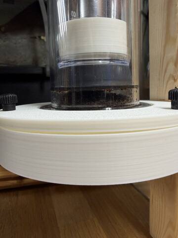
The chamber-end design skipped a generation: instead of the single-purpose telescope receiver, a rim brim hosting both inputs got printed — grounds port and water port on opposite sides of the chamber mouth, both at 60°. The spout sockets directly into the Ø30 grounds port (hard joint; the Ø38–40 telescope with an air gap stays the v2 option if removal gets annoying), and the water port wraps the Ø13 silicone line from the Tiger — the tube's own compliance is the vibration decoupling on that side. Opposite-side entry delivers the offset-pour swirl the no-stirring design counts on. This is the Phase 4 "rim manifold" arriving a phase early, and it closes the oldest integration to-do: the dispense line no longer comes off by hand before pressing. Photos in the gallery.
Clearance test passed (08-20): with everything plumbed, the plunger jog-stepped down from home — 8 s approach at 30 %, then 1.5 s jogs through the critical zone — and the seal passed both port nozzles and the brim's inner ring with zero contact, into the bore. The brim is a fixed, press-safe part: nothing gets removed for a press. Next up, the remaining shakedown: dose through the brim, water through the brim (swirl + splash check at 32 mL/s), then the first full hands-free brew cycle.
-
The drawer spout is printed and in place: Ø26 ID / Ø30 OD round exit lofted from the rectangular drawer mouth (Fusion lesson re-learned: Shell fails on lofts — build hollow ducts as two lofts and Combine-Cut). Ø26 flows a steady stream with no bridging, even with RDT-damp grounds. But the session turned into a diagnosis: delivered weight declined dose-over-dose (1.41 → 1.23 g/s) until the culprit surfaced — over-spritzing. Repeated RDT on the same hopper load cakes damp fines at the spout entrance, and a loosely-seated spout rattling under grinder vibration made it worse. New rules: RDT is 1–2 light mists per hopper fill, at fill time only; seat the spout firmly; when the rate droops, brush the grinder exit + spout entrance and re-baseline with a 10 s dose.
After cleanup the path settled at ~1.40 g/s delivered (vs 1.50 caught at the drawer) —
grind_dur_msis now 11400 ms for a 16 g dose. The honest envelope for time-based dosing is ~±10% across bean, moisture, and cleanliness — exactly the ±1 g the design budgeted, and exactly why the load cell stays the by-weight endgame. Chamber-end design also firmed up: the catch funnel evolves into an angled telescope receiver on the rim collar (Ø40 ID, Ø46 flared mouth, 12–15 mm overlap, ~5 mm air gap) — enclosed against static scatter but never touching the spout, keep-out column untouched. That's the next print. -
Live calibration session over REST: 10 s doses fired remotely, weighed on the 0.1 g scale between runs. First finding — static is a real problem, so RDT is now part of the loading routine (a light water spritz on the hopper beans); it killed the cling and the variance with it. The dry primer dose on empty burrs ran 3 g light and was dropped as an outlier. At the dial's starting position (21): 18.0 g and 18.0 g — 1.80 g/s. Then the dial went to 14, the AeroPress baseline, turned mid-spin per Baratza's rule, and the finer grind fed slower: 15.0 g and 15.0 g — 1.50 g/s, with 0.0 g spread on every pair, well inside the ±1 g budget.
grind_dur_ms= target grams ÷ 1.5 × 1000 → set to 10667 ms for a 16 g dose (1:15.6 with the 250 mL pour) and the validation dose landed 16.0 g exactly. The rate is tied to setting 14 + RDT — any dial move or skipped spritz means a re-fit (two 10 s doses, minutes of work). Bonus: RDT may make the grounded stainless chute liner unnecessary — a candidate simplification for the Phase 4 rim collar. Remaining in Phase 3: the 20-dose repeatability gate and the spout + catch-funnel prototypes. -
2026-08-16decision
Architecture simplified — Raspberry Pi and custom web app dropped, Home Assistant instead
¶The planned Pi + FastAPI/SQLite/HTMX web app is out. The realization: the machine has run Pi-less through the entire bench program — the ESP32 already owns all control and every calibrated parameter — and the Pi's remaining value (brew history, graphs) is exactly what Home Assistant provides natively over the ESPHome API, with zero custom code. Phase 6 re-scoped to firmware + an HA hookup: recipe presets, tank-level tracking with feed-forward dispense compensation (the ~65 mL drift fix moves on-device), optional scheduling, and a monochrome front panel — SSD1322 256×64 OLED + physical Brew/Clean buttons, rotary encoder a maybe (soft call, same day). The Phase 7 touchscreen kiosk retires with the Pi. Nothing in firmware assumes HA exists, so the machine stays fully functional standalone — and the old plan stays documented if it's ever revived.
-
The relay box arrived and went straight through bring-up: GPIO14 → opto-isolated control input, Encore's front switch latched ON into the "normally OFF" outlet. Tested lamp-first: manual toggle, a 5 s timed dose that shut itself off, and dark through a physical ESP32 reset (the boot-safety check that matters). The 75 s watchdog fired on cue — relay forced off with the ERROR line captured in the event stream. Then with the Encore in: clean 2 s spin, and Grinder Stop killed a 10 s dose at ~3 s with the relay staying off past the dose's would-be end — the stopped script's tail can't re-fire it. No mains ever touches the bench; the enclosed relay box is the only thing that sees 120 V.
Also this week: the grounds drawer is printed and fits the Encore's bin recess — first physical piece of the delivery path — and the delivery design is split into drawer spout → 10–15 mm air gap → gravity-seated catch funnel on the chamber rim (
docs/phase3-spout-catch-concept.svg; the funnel lifts off by hand for now, its Phase 4 successor is the zero-overhang rim collar). Next: dose calibration by weight (3× 10 s doses, fit g/s), then the spout + funnel prototypes. -
Phase 3 starts in parallel with Phase 2's remaining wet re-tunes, and the plan's gutted blade grinder is out: the Baratza Encore is in — burr-quality grind from day one, with the Tiger philosophy intact: the appliance stays electrically untouched. Its front switch latches ON and the ESP32 switches the grinder's mains upstream through an enclosed opto-isolated relay box (Adafruit #2935, the rebranded DLI IoT Power Relay) for time-based dosing. The load-bearing assumption — the Encore restarts when power is applied — verified by hand: connect = grind, disconnect = stop, repeatable.
Firmware shipped the same day:
grinder_power(boot-forced OFF),grind_dur_ms, Grind Dose / Grinder Stop buttons, and a 75 s watchdog armed on every on-path. Grounds-delivery concept drawn up: printed carrier + grounded stainless liner against static (docs/phase3-encore-chute-concept.svg). -
Filled the AeroPress from the Tiger dispense (250 mL) and brewed end-to-end with the new 3-phase Brew Press. The breakthrough: a fast seal plunge (6000 ms @ 70 %) + a ~5 mm backoff pulls a vacuum that held the water through a full 90 s steep with no overflow — without it the paper filter just drains the pour. That suction-hold is what makes a stationary-chamber auto-AeroPress actually work. The slow extract pressed the coffee through; the hiss came at ~26000 ms (Press Duration set to 20000, just short of it).
Eject finding: the planned pneumatic eject (trapped air pops the puck, plunger stays clean) doesn't work — by eject time the water's pressed through, so the spent damp-grounds puck won't seal the bore and the air just leaks past instead of pushing. Contact ejection is the answer: drive the seal down to push the puck out, accept a little coffee on the silicone seal (the Phase 5 spray clean handles it). This makes the "stop before the hiss for an air gap" idea moot, so the extract can press closer to the hiss for fuller extraction next time.
press_eject_msneeds a wet re-tune as a contact-push distance. -
Wrote the open-loop timed press-cycle firmware (home / descend / press / eject scripts, tunable durations, bench buttons, boot-safe, Stop aborts all) and calibrated it dry against the bench: approach 12000 ms lands the plunger right at the chamber mouth, eject 36000 ms drives through and out the bottom (clean pass), home 50000 ms full return — and the full cycle chains cleanly. All times are tied to the 30 % travel speed (re-scale if that changes).
The real sequence is two stages with a manual step between, not one auto cycle: (1) Brew Press — descend and press to ~80 % / the AeroPress hiss, then stop, leaving an air gap above the puck; (2) the user swaps mug → waste cup and removes the filter cap + bottom plate; (3) Eject & Clean — press a short bit further so the trapped air pneumatically pops the puck out the open bottom, and the seal never touches the grounds — the plunger stays clean. The "hiss" can't be sensed open-loop (approximated by a calibrated depth; current-sense is the honest fix later), and the real eject is a small partial press, not a drive through — so the auto "Full Cycle" is now just a bench-test button.
Press Durationand the partial eject are wet-tuning tasks (need a real brew to press against). Buttons relabeled Brew Press / Eject & Clean / Home Plunger. -
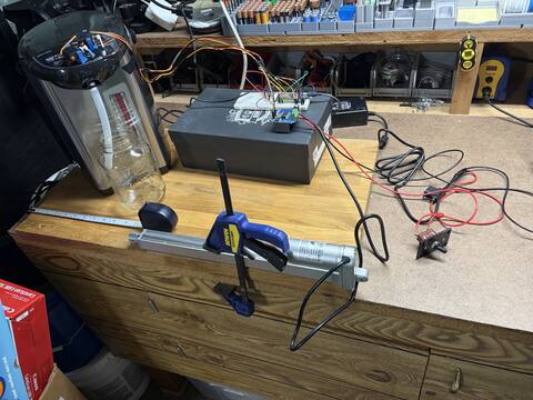
Mount, cradle, and plunger coupler built from printed parts; the plunger is aligned to the chamber and dry test push-throughs run under actuator control with no binding. Alignment was solved by fitting the existing printed parts — after a good run through the options: an offset clevis-hole adapter (dropped — the actuator rod can spin, so a fixed offset would point in a random direction), a single-axis slotted alignment plate + shim, and a funnel + floating coupler for mechanical self-centering. The slotted-plate and funnel/float concepts are saved in
docs/as fallbacks if alignment ever drifts.MVP decision: no external limit switches (step 2 deferred). The press runs open-loop — actuator ends are known via its internal limits, press depth is a timed move homed from full retract. Current sensing on the BTS7960 is the cleaner future upgrade for end-of-press + over-force.
Integration to-do (Phase 4): the dispense hose currently has to be pulled by hand before pressing or it blocks the plunger. The fix is the documented offset pour — mount the hose at a fixed offset, angled into the chamber beside the plunger's column, so nothing moves out of the way (and the off-center pour adds extraction swirl). Next on the bench: press-profile tuning (step 4) and puck ejection (step 5).
-
The whole press drive chain is proven end to end: ESP32 → BTS7960 H-bridge → Firgelli 150 lb / 12 in actuator off the 12 V brick. Wired RPWM/GPIO9 (extend), LPWM/GPIO10 (retract), the tied enables on GPIO11 (boots LOW, fail-safe), and common ground to the ESP32; the brick is spliced straight in (no barrel jack on hand) through the 10 A fuse + kill switch. The 12 V supply was a splice job — verify polarity with a meter, never trust the wire markings.
Firmware added to
coffee-bot.yaml(boot-disabled enable, never-both-directions scripts, jog + run + stop bench buttons) and flashed OTA via a freshly-installed ESPHome 2026.6.1. Result: full-stroke extend and retract under web-UI control, internal end-stops hold both ends, and Actuator Stop halts it instantly mid-travel. No brownout — the 12.5 A brick swamps the 8 A surge. Phase 1 servos untouched. Next: measure the actuator, build the stand, fit the limit switches (step 2). -
Ran the step-8 full→¼ tank sweep (15 weighed pours,
logs/flow_sweep_20260613.csv) — the last Phase 1 loose end. Result: pour volume drifts ~65 mL from full (~312 mL) to ¼ tank (~247 mL), roughly linear at ~17 mL/L drained. That's ~4× the ±15 mL pour-to-pour spec, so the dominant volume error isn't pump spin-up noise — it's tank level. And since ¼ tank is the normal refill point, that whole span is the real operating envelope. The drift is at least systematic and predictable: over-pours when freshly filled, drifts to on-target by refill time.The fix is not re-tuning the open-loop model (it's already stale — upper-tank pours read ~37 mL above the 06-05 calibration, the 06-11 spout/hose rework shifted the plumbing). Two layered fixes instead: (1) app-side feed-forward compensation — the Pi already commands every pour, so it tracks water dispensed since refill, estimates tank level, and adjusts the per-pour dispense time off this measured drift curve; cancels the systematic ~65 mL, leaving ~±15 mL, and gives a tank fill bar + refill prediction in the UI for free. (2) load-cell closed loop — stop the pour at target weight; kills both error sources to ±5 mL and enables by-weight dosing. They stack (feed-forward + feedback), and the load cell stays a deferred upgrade since software comp covers v1. (2026-08-16: the Pi was later dropped — this compensation now lives in ESP32 firmware; same math, different host.)
With this, native-button check, and threadlock all done today, every Phase 1 step is resolved and Phase 2 (press mechanism) is the active phase — drive-chain parts ordered.
-
BOM written (
hardware/phase2-bom.md) and the drive chain ordered: Firgelli 150 lb / 12 V / 12 in actuator (0.30 in/s, IP66, 5 A draw / 8 A surge), BTS7960 (IBT-2) 43 A H-bridge with fail-safe enable wiring, a 12 V / 12.5 A UL-listed sealed brick sized for the surge, and 16 AWG power wire. Base is a butcher-block + braced 2×4/plywood bench fixture (aluminum baseplate deferred to Phase 4 / wet path). Safety adds the scope didn't list: inline 10 A fuse + a 12 V kill switch — this phase's hazard is mechanical crush, not electrical. -
50 consecutive
brew_dispensecycles, zero failures, zero manual interventions, zero safety events — the Phase 1 exit criterion, met. Single ~1 h session over the recirculation loop (20:30–21:28, 43 s/cycle cadence), all 50 REST triggers accepted, servos parked clean, bench dry and tank level constant at the end. Log:logs/endurance_20260611_203015.csv. The unlock press (re-landed at 0.53 the same day) held its geometry through all 50 presses — no drift.Harness gotcha for the record: cycles 16–20 stalled for up to 18 min when the bench Mac napped and suspended the script mid-run. Fix: pin the Mac awake with
caffeinate -i -w <script pid>(now noted in the script header). The stalls were idle gaps between cycles — each dispense itself was unaffected.Phase 1 is done. Loose ends carried forward: confirm the Tiger's native buttons still work under the bracket (step 5), confirm threadlock on the unlock horn, and decide whether the full→¼ tank flow sweep (step 8) still matters now that ±15 mL is the accepted v1 tolerance. Next: Phase 2 — the press mechanism.
-
First smoke cycle of the recirc loop leaked: the uphill tube run to the fill opening puts static head on the spout (the first back-pressure it has ever seen — open-air dispensing never pressurizes it), and water exited through a thin gap along the back of the nozzle that the slip-over hose seal couldn't cover. Silicone caulk was considered and rejected (not food-safe, and it would glue the spring-loaded spout solid).
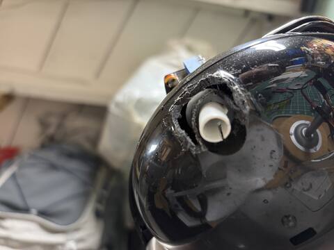
Fix: relieved the housing plastic around the spout with a Dremel for hose clearance, dealt with the flared features on the nozzle that broke the seal line, and zip-tied the silicone hose over the sealed zone. Smoke cycle after the fix: clean, no leaks, return flowing into the fill opening. Trade recorded: the Tiger is no longer cosmetically unmodified — the spout housing is permanently relieved. Electrical isolation and the appliance's internal safety stack are untouched.
Same session: the 06-10 unlock regression was resolved by re-tuning — unlock press re-landed at 0.53 (third value: 0.65 → 0.55 → 0.53).
-
The unlock servo stopped landing its press again (same mode as the 0.65 → 0.55 drift on 06-05; threadlock was still pending). Diagnosis fork: hand-press the button (rules out the Tiger side) → fire
Test Unlock Pressand watch where the tip lands — short/off-center means the horn screw backed out or the horn re-seated a spline tooth off (~18°/tooth ≈ 0.2 level units, much bigger than the earlier drift); skating past the button means the sweet spot moved again; square press but no unlock means dwell/depth, not geometry. Also check the bracket hasn't shifted on the panel.Likely fix beyond re-tuning: a 3D-printed clamp-over extension on the stock horn (don't print the spline — FDM won't hold the 20-tooth 4.8 mm spline). Paddle or cupped face larger than the button so small drift still presses center-ish; ideally a constant-radius cam face so overtravel adds preload instead of skating off. Add the silicone pad the pin-assignments doc already planned. Threadlock the screw the same session, before the endurance run.
Same-day pre-flight while diagnosing: board up, all five calibration numbers persisted (250 / 32.0 / 1750 / 0.45 / 0.55). Gotcha found: curl on the bench Mac intermittently fails to resolve
coffee-bot.local(ping resolves fine) — run the endurance script withHOST=192.168.1.19. -
This site: phases 0–8 with sub-step statuses, per-phase wiring diagrams, decisions log, pinout/BOM/safety/risk reference, bench cheat-sheet. Static single file, S3 + CloudFront, deployed via
webapp/deploy.sh. -
scripts/endurance_run.sh: fires Nbrew_dispensecycles over REST with CSV logging, pre-flight reachability check, consecutive-failure abort, Ctrl-C parks the servos. Assumes a recirculation loop (spout tube routed back into the Tiger's fill opening) so 50 cycles don't need 12.5 L of catch vessel. Smoke test: cycle 1 ok. -
Temperature monitoring removed from firmware — the UL-listed Tiger self-regulates and nothing in the dispense path consumes the reading (the bench probe had also died after a water dunk). And the measured ~±15 mL open-loop pour spread is accepted for v1: it's pump spin-up variance + tank drift, untunable by timing, ~6% of the water. ±5 mL deferred to a load-cell + HX711 closed loop. Details in the decisions log.
-
Compiled (ESPHome 2026.5.2), flashed over UART, on WiFi at
coffee-bot.local; OTA from here on. Servos calibrated in-place against the Tiger's buttons (unlock 0.55, dispense 0.45 — 0.65 overshot the unlock contact arc after a reboot). Dead-time dispense model fitted: 32.0 mL/s + 1750 ms, centered ~250 mL. Auto-relock measured ~10 s — the 300 ms unlock→dispense gap has ~33× margin. Gotcha of the day: servo PSU ground must tie to ESP32 ground — without it both servos spin continuously. -
Both MG90S units press the Tiger's buttons with force to spare (standalone servo-tester rig) — the button-press architecture is feasible before committing to bracket design. Parametric bracket modeling started in Fusion 360; decided on stock horns with arc-tuned press geometry.
-
A UL-listed appliance takes over all thermal regulation and mains safety — trades arbitrary setpoints for fixed ones (196 °F is well-centered for AeroPress) and cuts most of the Phase 1 electrical risk and timeline.
Photos
Build photos
The build in pictures, oldest first — from Phase 1 wiring to the fully-plumbed delivery train. Click any photo to zoom (arrow keys navigate). Originals plus a couple of clips live in the repo's images/build/ folder.
Phase 0 · complete
Planning & sourcing
Lock the design enough to start buying parts, and get the development environment ready. Everything downstream depends on the architecture choices made here — the control split, the stationary layout, and the staged build discipline.
Tasks
-
done
Finalize the scope document and system architecture
Full plan in
coffee-bot-project-scope.md— nine phases, each with an exit criterion, plus the risk register and decisions log. Control split (Pi UX / ESP32 real-time) and stationary mechanical layout locked. -
done
Choose specific Phase 1 components
The big call: a UL-listed Tiger PDU-A50U hot-water dispenser instead of a gutted kettle + SSR + PID, interfaced by servos pressing its buttons (2026-05-27 / 05-31 decisions). ESP32-S3-DevKitC-1 N16R8 as the controller. Full list in Hardware & BOM.
-
done
Set up the dev environment and repo structure
ESPHome 2026.5.2 installed; repo laid out as
firmware/,webapp/,hardware/,docs/; secrets insecrets.yaml(never committed). -
done
Order Phase 1 parts
No long-lead items — everything ships in 1–3 days (McMaster silicone next-day). ~$435 from scratch, ~$325–365 net of already-owned tools.
-
done
Acquire safety equipment
Inline GFCI adapter (15 A), surge protection, multimeter, Class C fire extinguisher within reach for all powered testing.
Wiring
No wiring in this phase — it's all paper and purchase orders. The wiring story starts in Phase 1.
Phase 1 · complete
Water heating + dispense
A benchtop rig that holds water at an AeroPress-appropriate setpoint and dispenses ~250 mL on command, failing safe under any single-point failure. The most dangerous and most foundational subsystem — which is why it goes first.
logs/endurance_20260611_203015.csv. See the build log.Architecture
A stock Tiger PDU-A50U 5 L hot-water dispenser does all the heating — it's UL-listed, holds its setpoint 24/7 by design, and keeps its own thermal protection stack (thermostat, thermal fuse, dry-fire interlock). The ESP32 never touches mains or water. It drives two MG90S micro servos in a printed PETG bracket clipped over the Tiger's button panel; the servos physically press Unlock (the child-lock can't be disabled, and re-arms in ~10 s) and Dispense (held for the calibrated pour duration). The Tiger is electrically untouched — no soldering, no teardown, its internal safety stack intact. One permanent cosmetic mod (06-11): the housing plastic around the spout was relieved with a Dremel so the recirc/dispense hose can seal past a gap in the nozzle.
Pour volume is open-loop timed using a dead-time model: hold = volume / flow + dead_time with flow = 32.0 mL/s and dead-time = 1750 ms (pump spin-up + tube priming). The dead-time term is what keeps small bloom and pulsed pours proportional, not just the 250 mL target. Water exits the spout through slip-over food-grade silicone tubing (10 mm ID over the 10.5 mm OD spout).
Unlock press level
Third value (0.65 → 0.55 → 0.53) after the 06-10 geometry walk. Held through all 50 endurance presses with no drift.
Dispense press level
Held for the full pour; minimal overtravel to avoid a sustained stall.
Flow rate
Two-point fit at 196 °F. Varies with tank level — full→¼ sweep still pending.
Dead time
Pump spin-up + priming lag, net of end-of-pour dribble. Fitted from 15.0 s→421 mL, 8.9 s→226 mL.
Measured data from logs/ · re-render with scripts/render_charts.py
Step-8 sweep (15 weighed pours, logs/flow_sweep_20260613.csv): pour volume tracks tank level almost linearly — the systematic ~65 mL drift the Phase 6 feed-forward compensation (firmware-side since the 2026-08-16 Pi drop) will cancel. Scatter at a fixed level is the accepted ±15 mL.
Exit-gate endurance run (logs/endurance_20260611_203015.csv): 50/50 cycles at a steady ~43 s cadence. The spikes are the bench Mac napping between cycles — idle gaps, not rig failures; the harness now runs under caffeinate.
Build sequence
-
dropped · v1
1. ESP32 + DS18B20 temperature verification
Dropped 2026-06-08. The Tiger self-regulates its setpoint, so an independent probe was never control or safety — just a monitoring nicety. Removed from firmware (was GPIO4); the bench probe had also failed its OneWire bus after a water dunk. Re-add later as a food-grade in-tank probe if wanted.
-
done
2. Servo bench test
Both MG90S units validated standalone (servo tester, 06-03) with enough torque to depress the Tiger's buttons, then driven from the ESP32's LEDC PWM on a separate 5 V/2 A supply (06-05). The gotcha was the common ground — without tying the servo PSU ground to the ESP32, both servos spun continuously.
Exit: reliable ESP32-driven sweep, no brownout, quiet at rest. ✓
-
done
3. Dispenser baseline verification
Out-of-box function confirmed before any hardware went near it (non-negotiable — a DOA unit caught early is returnable). Auto-lock re-arm window measured at ~10 s, which gives the firmware's 300 ms unlock→dispense gap ~33× margin. Tiger set to 196 °F and left powered 24/7 as designed (~1 kWh/day standby).
-
done
4. Servo bracket design + print
Parametric Fusion 360 model; PETG print clips over the button panel with no fasteners or adhesives. Stock single-arm horns, shaft axis parallel to the panel so the horn sweeps into the button, contact landing near end-of-travel where tip motion is straight in (minimal skate, max torque).
-
done
5. Servo press calibration + validation
Servos mounted and calibrated in-place via the web UI test buttons: dispense 0.45, unlock now at 0.53 — third value after two geometry walks (0.65 → 0.55 → 0.53; the 06-10 regression was resolved by re-tuning, 06-11). The fix held through all 50 endurance presses with no drift. Closed 2026-06-13: unlock horn threadlocked, and the Tiger's native buttons confirmed still working with the bracket installed.
-
dropped · v1
6. DS18B20 body mount + offset calibration
Dropped with step 1. If a probe returns later, it should be a food-grade in-tank unit reading true water temperature — no body-offset calibration needed.
-
done
7. Slip-over silicone tube on the spout
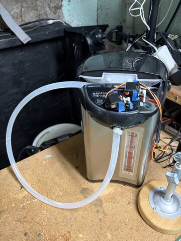
Heat-softened 10 mm ID tube installed two-handed against the spring-loaded spout's flex, routed forward-and-down with strain relief near the spout exit. For endurance testing the tube is routed back into the Tiger's fill opening as a recirculation loop, so tank level stays constant across 50 cycles (~12.5 L of water otherwise). Sealing fix (06-11): the recirc back-pressure leaked through a gap in the spout's nozzle — housing relieved for hose clearance, flares addressed, hose zip-tied over the sealed zone. No leaks through the 50-cycle run.
-
done
8. Flow-rate characterization
Steady-state flow 32.0 mL/s and 1750 ms dead-time fitted at 196 °F. Full→¼ tank sweep done 2026-06-13 (15 pours, weighed;
logs/flow_sweep_20260613.csv): pour volume drifts ~65 mL from full (~312 mL) to ¼ tank (~247 mL), roughly linear at ~17 mL/L drained — ~4× the ±15 mL spec, so tank level (not spin-up noise) is the dominant volume error across a refill cycle. The drift is systematic and predictable (over-pours when freshly filled, on-target near refill), and ¼ tank ≈ the normal refill point, so this span is the real operating envelope. Upper-tank pours read ~37 mL above the 06-05 calibration → the 06-11 spout/hose rework shifted the plumbing; the open-loop model is stale. Fix is not open-loop re-tuning — it's feed-forward tank-level compensation (near-term; firmware-side since the Pi was dropped 2026-08-16) and/or the load-cell closed loop (precision). See the decisions log. -
done · v1
9. Volume calibration
Centered near 250 mL; repeat pours of 261/237/237 mL show an open-loop spread of ~±15 mL, dominated by pump spin-up variance plus slow tank-level drift — not tunable by timing. Accepted for v1 (~6% of the water, imperceptible in an AeroPress). ±5 mL is deferred to the load-cell closed loop (stop the pour at 250 g).
-
done
10. Endurance test — the exit gate
scripts/endurance_run.shfires Nbrew_dispensecycles over the REST API with CSV logging, a pre-flight reachability check, consecutive-failure abort, and a clean Ctrl-C that parks the servos. Passed 2026-06-11: 50/50 cycles in a single ~1 h session over the recirc loop — zero failures, zero interventions, no leaks, no servo drift, bench dry at the end. Log:logs/endurance_20260611_203015.csv. (Run the script undercaffeinate— a sleeping Mac suspends it mid-run.)Exit: 50 consecutive successful cycles, no manual intervention, no safety events. ✓ Phase 1 complete.
Wiring diagram
The ESP32 side is entirely low-voltage; the only mains-connected component is the stock appliance behind a GFCI.
restore: false keeps boots deterministic. A reset, brownout, or crash can therefore never press a button: the failure mode is “no press,” never “stuck pressing.” on_boot re-asserts rest as belt-and-suspenders, and there's deliberately no auto_detach_time — a detached arm could drift onto a button, and a detach mid-pour would cut the dispense short.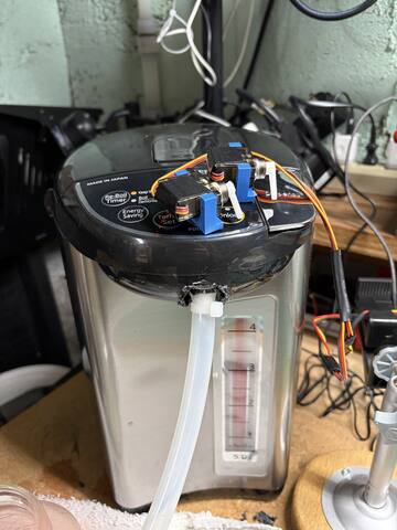
Considerations
- Setpoint is manual, held 24/7. 196 °F covers all AeroPress recipes; 176 °F-style recipes wait for a third servo or teardown. Standby ≈ 1 kWh/day (~$5/mo).
- Unlock before every dispense. The child-lock can't be disabled and re-arms in ~10 s. The firmware's 300 ms gap has ~33× margin; the relock does not interrupt an in-progress pour (confirmed).
- Gentle stall only. The horn bottoms out with slight overtravel and a brief stall — a sustained hard stall cooks MG90S gears. Threadlock the horn screws; they back out under press-and-stall cycling.
- Spring-loaded spout. It flexes toward the tank when pushed. Two-handed tube install, route forward-and-down, strain-relieve within 2–3″ so tubing forces never load the spout's internal spring.
- Tank level moves the pour. Pump output drops as the tank empties — part of the measured ±15 mL. Step 8's sweep quantifies it; the load-cell upgrade makes it irrelevant.
- Tube geometry is part of the calibration. Any Phase 4 plumbing change means re-running flow characterization.
Phase 2 · current focus
Press mechanism
Drive the AeroPress plunger through a full press stroke with controlled force and position — including pushing the spent puck out the bottom — with hard limit interlocks the firmware cannot ignore.
Architecture
A Firgelli 12 V linear actuator (12 in stroke, 150 lb force, 0.30 in/s, IP66) hangs above the cradle and couples to the plunger through a printed PETG coupler (fine here — an air gap separates the plunger from the coffee). A BTS7960 (IBT-2) H-bridge gives direction + speed control, with the enable line defaulting low at boot so the actuator can't move until firmware allows it; top and bottom limit switches feed the ESP32 as interlocks. The AeroPress sits in a rigid printed cradle on a butcher-block + braced 2×4/plywood bench fixture that has to shrug off 30–40+ lb of press force without flexing (the anodized-aluminum baseplate is deferred to Phase 4, where it joins the permanent wet path). Power is a 12 V / 12.5 A UL brick through an inline 10 A fuse and a manual kill switch.
Build sequence
-
done
1. Wire actuator + H-bridge + 12 V supply
Verify extend/retract under ESP32 control. Done 2026-06-18: BTS7960 wired to GPIO9 (RPWM/extend), GPIO10 (LPWM/retract), GPIO11 (tied R_EN+L_EN, boots LOW), common ground to the ESP32; 12 V/12.5 A brick spliced through a 10 A fuse + kill switch to B+. Firmware flashed (ESPHome 2026.6.1, OTA). Actuator extends and retracts full-stroke under web-UI control, the internal end-stops hold both ends, and Actuator Stop halts it instantly mid-travel (drops the enable → motor coasts). No brownout — the 12.5 A brick has ample headroom over the 8 A surge.
-
deferred · MVP
2. Add limit switches as hard interlocks
Deferred for the MVP (2026-06-23): the press runs open-loop — the actuator knows its two ends via internal limit switches, and press depth is a timed move (0.30 in/s) homed from full retract. External switches aren't wired. The cleaner future upgrade is current sensing on the BTS7960 (R_IS/L_IS) for end-of-press-by-load + over-force protection — see the build log. Drawing kept:
docs/phase2-actuator-limit-switch-layout.svg. -
done
3. Mount AeroPress in cradle, couple the plunger
Verify alignment and zero binding through the full stroke. Done 2026-06-23: mount, cradle, and plunger coupler built from printed parts; plunger aligned to the chamber and dry test push-throughs run under actuator control with no binding. (Alignment was solved mechanically by fitting the existing parts — the offset-adapter idea was dropped once it was clear the actuator rod can spin, which would point a fixed offset in a random direction. The slotted-plate and funnel/float concepts in
docs/are kept as fallbacks.) -
in progress
4. Tune press profile — 3-phase, wet-validated
Validated on a real 250 mL brew (2026-06-25). The Brew Press is 3 phases: (1) Seal Plunge — fast (6000 ms @ 70 %) to ~7 mm past the mouth, to engage the seal before the filter drains; (1b) Backoff — a ~5 mm retract that pulls a vacuum holding the water through the full 90 s steep (the key enabler — without it the pour just drains out); (3) Extract — slow (30 %) press toward the hiss (found ~26000 ms; Press Duration set to 20000). "Hiss" can't be sensed open-loop (calibrated depth; current-sense is the honest detector later); the press is much slower under brew back-pressure (~1.3–2.2 mm/s vs ~3.3 free-air).
-
in progress
5. Puck ejection — contact push
Revised after the wet test (2026-06-25). The planned pneumatic eject (leave an air gap, let trapped air pop the puck so the plunger stays clean) doesn't work — the spent, drained puck won't seal the bore, so the air leaks past instead of pushing. Contact ejection is the answer: drive the seal down to push the puck out the open bottom; a little coffee ends up on the food-grade silicone seal, which the Phase 5 spray clean handles. The puck did eject this way.
press_eject_msneeds a wet re-tune as a contact-push distance. -
todo
6. Endurance — 50+ press + eject cycles
Water-only AeroPress, full stroke every time, limit switches respected on every cycle.
Wiring diagram tentative — pins finalize at phase start
Direction comes from which PWM pin is driven (RPWM extend / LPWM retract); both enables tie together to GPIO11. Limit switches are inputs with internal pull-ups, switched to ground.
Concept drawings docs/ — to scale · fallbacks + future upgrades
 actuator mount layout
 limit-switch layout (deferred)
 alignment plate (fallback)
 funnel + floating coupler (fallback)
Considerations
- Cradle rigidity is the whole game. 30–40+ lb of press force; any flex shifts the AeroPress and binds the plunger.
- PETG coupler is fine — air gap between plunger top and coffee means it never touches the food path.
- Current sense (optional) enables end-of-press detection by load and nicer press profiling later; a stepper + leadscrew is the eventual upgrade path for true press profiles.
- Park position: on any fault the actuator parks (retracted) — rule 8 of the safety constraints.
Phase 3 · in progress
Grinder integration
Dose a repeatable quantity of ground coffee on command. A Baratza Encore, electrically untouched — front switch latched ON, its mains switched by the ESP32 through an enclosed relay box — with time-based dosing and grounds out a chute. The burr grinder landed early: the Encore replaced the planned gutted blade grinder, same appliance-untouched philosophy as the Tiger.
Build sequence
-
done
1. Switch the grinder's mains through an enclosed relay
No gutting: the Encore stays electrically untouched. Its front switch latches ON and GPIO14 drives the opto-isolated control input of an enclosed relay box (Adafruit #2935 / DLI IoT Power Relay, "normally OFF" outlet) — no mains ever on the bench. Done 2026-08-14: restart-on-power-apply verified 08-06; wired and lamp-tested (toggle + 5 s timed dose), stays dark through a physical ESP32 reset.
-
done
2. ESP32 controls grinder run time
A switch entity + scripted run duration, with a hard maximum runtime as a guard. Done 2026-08-14:
grinder_power(boot-forced OFF),grind_dur_mstimed dose, Grind Dose / Grinder Stop buttons, 75 s watchdog armed on every on-path. Verified live: clean 2 s spin, mid-dose Stop abort with no script-tail re-fire, watchdog force-off at 75 s with the ERROR logged. -
done
3. Build the time→grams curve
Grind for N seconds, weigh the output, fit the rate. Done 2026-08-16: 1.50 g/s at grind setting 14 (AeroPress baseline) with RDT —
grind_dur_ms= grams ÷ 1.5 × 1000, set to 10667 ms and validated at 16.0 g dead-on. Static was a real problem → RDT adopted (light water spritz on the hopper beans at load). The rate is tied to setting 14 + RDT: setting 21 measured 1.80 g/s, so re-fit after any dial move (turn the dial only while the motor runs). Dry primer dose on empty burrs ran 3 g light — expect that after any burr-chamber cleanout. -
todo
4. Test repeatability across 20 doses
±0.5–1 g is the accepted v1 spread. By-weight dosing (load cell under the chamber) is the upgrade that fixes this properly — same HX711 hardware as the dispense upgrade.
-
in progress
5. Design and test the chute
Grounds must fall cleanly without clinging: steep angle (>60°), smooth surface, removable for cleaning. Nearly done (2026-08-20): drawer + spout printed and validated (Ø26 ID / Ø30 OD round exit, steady stream, no bridging), and the chamber end skipped ahead to a rim brim hosting both inputs — grounds port (Ø30 ID, spout sockets in) and water port (wraps the Ø13 boiler line) on opposite sides at 60°, giving the offset-pour swirl for free. Plunger clearance test passed with everything plumbed — the brim is a fixed, press-safe part, and the Phase 4 "remove the hose before pressing" to-do is closed. Both ran, and the first full hands-free brew followed. Delivery v3 in design (2026-08-31): the rebuilt frame's shelf adds height, so the entry angle can go shallower (~45°) — a longer chute bleeds off speed, so grounds land instead of ricocheting off the far chamber wall — in a ~Ø23–26 polished stainless tube (low friction, no static once bonded, actually cleanable). Bore barely shapes the stream (the tube runs under 5 % full), so the collimating happens at the exit and a low shroud outside the Ø66 keep-out catches the rest; flexible hose was rejected (sag retains grounds, silicone is tacky and static-prone). Cardstock Ø20-vs-Ø26 A/B at 45° settles it before anything gets printed. (v2 option if removal gets annoying: open the grounds port to a Ø38–40 telescope with an air gap. Earlier concepts:
docs/phase3-spout-catch-concept.svg,docs/phase3-encore-chute-concept.svg.)
Wiring diagram as built 2026-08-14
Relay in the hot leg, normally-open: grinder is off on ESP32 reboot, crash, or brownout. Mains never touches a breadboard (safety rule 4).
Considerations
- Grinder motors are electrically filthy. Snubbers/flyback protection, sensor wiring physically separated from motor wiring, separate ground if EMI shows up in Phase 4.
- Retention is real: some grounds always stay behind. Accept it, or purge with a small pre-grind.
- Dry grounds vs the wet-path rule: a printed chute is acceptable (dry contact), but it still oils up — make it removable.
- Burr-quality grind was a planned non-goal for v1 (blade grinder) — then the Encore-untouched design made it free, so it landed early.
Phase 4 · planned
Mechanical integration
Combine heating/dispense, press, and grinder into one frame and run a full brew cycle end to end. Three individually-working subsystems can still fail together — timing interactions, mechanical interference, EMI, vibration. This phase is where the discipline pays off.
Mechanical layout
Stationary AeroPress, one vertical axis. Actuator on top, ~6 in open dispense zone below the retracted plunger (funnel and spray nozzle offset from the plunger axis, grounds chute entering from the side), chamber in a cradle on the baseplate, mug well below. Side-mounted: elevated boiler, cold reservoir, grinder + hopper, electronics, front panel. Footprint ≈ 11 × 12 × 27 in.

Side view, approximately to scale. The offset pour doubles as the stirring mechanism — see decisions.
Build sequence
-
todo
1. Build the frame
Aluminum extrusion or sheet metal. Rigidity is checked at the two load points: the actuator mount and the chamber cradle.
-
todo
2. Mount the actuator, verify travel
Plunger must clear the dispense zone fully retracted and reach through the chamber for ejection fully extended.
-
todo
3. Mount boiler (elevated), reservoir, grinder, electronics
Boiler elevation gives gravity assist; electronics go in a vented enclosure away from heat and splash.
-
todo
4. Position dispense funnel and grounds chute
Both offset from the plunger axis, both aimed into the chamber. Alignment is everything — grounds, water, and plunger all have to land in the same 62 mm circle.
-
todo
5. Route all tubing and wiring
P-clips and clean runs for silicone; strain relief and cable channels for wiring; sensor wiring kept away from motor wiring.
-
todo
6. Write the integrated brew state machine
idle → preheating → grinding → dosing_check → dispensing_bloom → blooming → dispensing_main → brewing → pressing → ejecting → idle, every transition guarded by precondition checks (at temp, water present, chamber seated, limits respected). -
todo
7. Dry run each step, then water-only, then a real brew
Escalate only when the previous level is boring.
System wiring map power domains + signals
Considerations
- Bloom timing: dispense ~20–30% of the water, pause 30–45 s, then the rest in pulses. Software-only, tunable per recipe.
- Thermal neighbors: the boiler warms nearby printed parts — PETG near heat, never PLA (softens ~140 °F).
- Vibration loosens everything — grinder and actuator both. Threadlocker, lock washers, periodic inspection.
- EMI from the grinder is the most likely "impossible" bug — plan wiring separation up front.
Phase 5 · planned
Cleaning system
The #1 failure mode of DIY coffee machines is that they get gross and get abandoned. An automatic cold-spray + hot-rinse cycle keeps daily grime handled, so manual cleaning is a weekly task — and the parts that need it pop out by hand.
Target cleaning cycle
Why cold spray? Coffee oils congeal in cold water and wash away; hot rinses can set tannin stains into plastic. The spray needs pressure (50–100 PSI diaphragm/washer pump), not just flow — peristaltics won't dislodge fines.
Build sequence draft — scope finalizes at phase start
-
todo
1. Bench-test pump + hollow-cone nozzle
Verify the diaphragm pump drives the food-grade nozzle with enough force to dislodge clinging fines.
-
todo
2. Solve spray geometry around the plunger
With a stationary chamber the plunger occupies the center — multiple jets around it, or side-mounted nozzles on the splash shroud hitting the walls.
-
todo
3. Waste drain at the chamber position
Rinse water exits the chamber bottom when the mug isn't there — drain to a waste reservoir with a level sensor so it can't silently overflow.
-
todo
4. Integrate hot rinse + cold spray into the state machine
The hot rinse reuses the Phase 1 dispense path; the spray pump gets its own MOSFET channel.
-
todo
5. Residue evaluation across 20 brew+clean cycles
Inspect the wet path; the cycle has to keep up with daily use on its own.
Wiring diagram tentative — finalize at phase start
Low-side MOSFET with a pulldown: pump is off at boot and on any reset (safety rule 7). The float switch is a hard precondition on the cleaning state.
Considerations
- No cycle replaces weekly manual cleaning — funnel, shroud, cradle, and chamber all pop out by hand. The reference DIY build failed because parts were uncleanable, not because it lacked a cycle.
- Optional spray-line solenoid if the pump alone doesn't give crisp start/stop.
- Mug logistics: cleaning happens with no mug present — that's why the waste drain exists at the chamber position.
Phase 6 · planned · re-scoped 2026-08-16
On-device UI + Home Assistant
The custom Raspberry Pi web app is dropped. Phase 6 is now firmware work plus a Home Assistant hookup: recipe presets, tank-level tracking with feed-forward dispense compensation, a monochrome front panel (SSD1322 OLED + physical Brew / Clean buttons), and HA — connected over the ESPHome native API — for brew history, graphs, and dashboards with zero custom code. The machine stays fully functional with HA absent.
restore_value) — the machine ran Pi-less through the entire bench program. The Pi's remaining value was history + graphs, which Home Assistant provides natively over the same API the custom app would have been built against, at a fraction of the effort. Low-risk: nothing in firmware assumes HA exists, and the old plan stays documented if it's ever revived.Architecture re-scoped 2026-08-16
Build sequence
- todo
1. Recipe presets
ESPHome
selectentity ("Standard / Strong / Small / …") — choosing one loads its values into the existing calibratednumberentities. A handful of presets, not unlimited CRUD. - todo
2. Tank-level tracking + feed-forward compensation
Global counter of mL dispensed since refill, a "Tank Refilled" reset button, and a lambda adjusting the dispense hold off the measured drift curve (
logs/flow_sweep_20260613.csv) — cancels the systematic ~65 mL tank-level error. Fill-bar sensor entity for the web page / OLED / HA. - todo
3. Home Assistant hookup
Point HA at the ESP32's native API (already configured with encryption). Recorder gives brew history and temp/state graphs; build one dashboard. Verify the machine is unaffected with HA down.
- todo
4. Front panel
SSD1322 OLED + physical Brew / Clean buttons; monochrome UI kept shallow (state, temp, progress, recipe pick). Rotary encoder only if it earns its place.
- todo
5. Scheduling (optional)
SNTP time +
on_timeautomation for a wake-up brew — or just an HA automation.
Wiring
New wiring is the front panel only: SSD1322 over SPI + two buttons on spare GPIO. The Home Assistant side is pure software — it joins over WiFi against I/O already in place from Phases 1–5.
Phase 7 · planned
Enclosure & polish
Turn the working mechanism into something that looks finished and is safe on a counter. Deliberately last: resist the urge to start here — it comes after the mechanism works.
Tasks
- todo
Design + build the outer enclosure
Printed panels, sheet metal, or both. Must not trap heat around boiler or electronics — ventilation matters. Removable panels, never glued: you will need to get back inside.
- todo
Enclose all mains wiring
Fully inaccessible during normal use; exposed metal bonded to earth.
- todo
Mount the front panel, tidy cable runs
SSD1322 OLED + Brew / Clean buttons from Phase 6 into the enclosure face (the planned touchscreen kiosk was retired with the Pi, 2026-08-16); cables into channels with strain relief.
- todo
Status lighting + cosmetic finishing
Anodized parts, consistent fasteners, splash containment and drip management refined. This is where it starts looking like the render.
The target
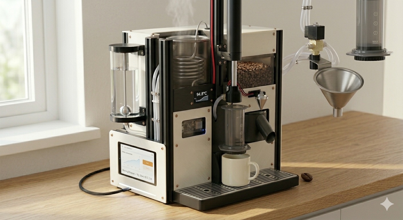
The concept render this phase aims at — the machine the bench rig grows into.
Wiring
No new circuits — this phase repackages Phase 4's wiring into enclosed, serviceable runs.
Phase 8 · the goal state
Daily use & refinement
Use coffee-bot every day and refine from real experience. The brew history + ratings become a dataset: A/B test dispense profiles, temperatures, and doses. Data-driven coffee is the fun part.
Ongoing work
- future
Use it daily, log issues
The ultimate test was in the success criteria from day one: it lives on the counter and gets used.
- future
Dial in recipes from history data
Overlay brews, compare ratings, converge on house blends.
- future
Watch for slow failures
Seal degradation, boiler scale (descale on a schedule), loosening connections, grounds accumulating in awkward spots.
- future
Upgrade deliberately — only once v1 is rock solid
Queue, in rough order of payoff: load cell + HX711 (closed-loop ±5 mL pours and by-weight dosing), burr grinder (motorized Baratza Encore), stepper + leadscrew press profiling, Home Assistant integration, scheduled wake-up brews.
Wiring
Only what upgrades bring. The load-cell upgrade adds an HX711 board on two GPIOs — it sits under the mug, outside the wet path, which is exactly why it beat a flow meter.
Reference
Decisions log
Every load-bearing call, dated, with the rationale and what it beat. The rejected option matters as much as the chosen one — it's the answer to "why don't we just…"
Dated decisions
Grounds path goes stainless — printed parts demoted to structure
The drawer adapter needs reprinting in something food-safe, but not like-for-like. The motivation is evidence rather than principle: the 08-17 session found damp fines caking at the spout entrance, and that retention — damp grounds sitting in layer lines between brews — is the realistic hazard in this path. Leached additives are not: contact is dry, seconds long, at ambient, and the result is brewed at 96 °C and paper-filtered. PLA's real disqualifier is that it softens around 60 °C, so the surface that most needs sanitizing can never take a hot wash. So the fix folds into the v3 chute instead of being a separate reprint: a stainless tube carries the grounds and the printed pieces become sockets and structure it passes through — the same "overlap, don't join" logic as the telescope, applied to materials. It collapses food safety, static, and wall friction into one fix, and it restores what the original Phase 3 concept specified (printed carrier + stainless liner) before the all-printed path got built. The Encore's rectangular exit → round transition is the one spot plastic is hard to avoid; first thing to try is a trimmed stainless kitchen funnel in a printed carrier (~$8, seamless) before any CNC quote. Anything that stays printed: PETG, thick solid walls, no interior supports, and a stainless nozzle rather than brass.
over: reprint the current geometry in PETG (thrown away when the angle and tube change) · food-contact epoxy interior seal (kept in reserve — coating a narrow duct evenly is fiddly, and a chipped coating is worse than none)
Staying with the Baratza Encore — no espresso-style grinder upgrade
A single-dose espresso grinder (DF54 class) looked like it would simplify grounds delivery. It wouldn't, and it would cost the machine its best property. The delivery problem is at the chamber end, not the grinder end — grounds arriving fast enough to cross the bore and ricochet out — and a new grinder leaves that untouched; its "spout" is a short near-vertical drop into a dosing cup, not a routable chute, so the chute still gets built either way. Worse, single-dosing means loading beans per brew, which hands back the hands-free operation the first full cycle just earned, and the bellows purge those grinders rely on is another manual step. Critically, the whole Phase 3 control scheme rests on the Encore's latching mechanical power switch (mains applied = grind); any replacement must do the same, or the opto-relay approach dies and the grinder needs modifying — which both appliances have so far avoided. Real wins forgone: lower retention and a clean round exit. But if dose accuracy is the itch, the load cell fixes it better, cheaper, and regardless of grinder — weighing the output beats improving the thing that meters it. 54 mm flat burrs are a genuine espresso upgrade and marginal for AeroPress.
over: DF54 / single-dose espresso grinder · criteria if this ever reopens, in priority order: latching power switch → hopper-capable → low retention → defined round exit; burr geometry last
Raspberry Pi + custom web app dropped — Home Assistant + on-device UI instead
The machine ran Pi-less through the entire bench program: the ESP32 owns all control and every calibrated parameter (restore_value). Every planned Pi job either moves into firmware — recipe presets (select → number entities), tank-level tracking + feed-forward dispense compensation, optional on_time scheduling, a monochrome front panel (SSD1322 OLED + Brew/Clean buttons, soft call) — or is covered by Home Assistant over the ESPHome native API: brew history, temp/state graphs, dashboards, with zero firmware changes and zero custom code. HA is an observer on any always-on box; the machine stays fully functional without it. Low-risk and reversible — nothing in firmware assumes HA exists, and the FastAPI/SQLite/HTMX plan stays documented in CLAUDE.md if it's ever revived.
over: custom FastAPI + SQLite + HTMX web app on a Pi (months of software for what HA's recorder provides natively) · Pi touchscreen kiosk (Phase 7) (retired with the Pi)
±15 mL open-loop tolerance accepted for v1; precision path = load cell
Measured pour-to-pour spread at the 250 mL target is ~±12–17 mL (261/237/237), dominated by pump spin-up variance + tank-level drift — timing tweaks can't beat it. That's ~6% of the water, imperceptible in an AeroPress. ±5 mL comes later from a closed-loop by-weight pour: load cell + HX711 under the mug, stop at 250 g. Immune to flow variance and tank drift, and the same part later enables by-weight coffee dosing.
over: more timing calibration (can't fix variance) · inline flow meter (food-safe sensor in the wet path is harder than a load cell outside it)
DS18B20 temperature monitoring dropped for v1
The UL-listed Tiger holds its own setpoint 24/7; nothing in the dispense path consumes an independent reading. The probe was never control or safety — just a nicety, and the bench unit failed its OneWire bus after a water dunk. Removed from firmware (GPIO4 freed). If re-added, it should be a food-grade in-tank probe reading true water temperature.
Stock servo horns + arc-tuned press geometry
No custom horn. Shaft axis parallel to the panel so the horn sweeps into the button; contact lands near end-of-travel where tip motion is straight in (minimal skate, full torque). Coarse alignment by spline indexing (~18° steps), fine by ESPHome level:. Committed only after bench-proving both servos had the torque.
over: custom-printed horn/pusher — simpler is adequate
Servos pressing buttons externally — not optocouplers inside
Two MG90S in a clip-on PETG bracket press Dispense and Unlock from outside. Eliminates the teardown entirely: no soldering into the appliance, no warranty/water-tightness/clip-breakage risk, fully reversible, native buttons still work. Cost delta +$13 net. Trade: no Temp Set actuation, so the setpoint is configured manually once (196 °F covers AeroPress; 176 °F recipes deferred).
over: optocouplers across the button taps (teardown, irreversible)
Slip-over silicone plumbing (10 mm ID × 13 mm OD, 50A, platinum-cured)
The Tiger's spout bore has an internal notch in hard plastic — a push-in seal is unreliable. Slipping a soft 10 mm ID tube over the smooth 10.5 mm OD exterior sidesteps the notch and preserves full flow area. 50A durometer for conformance; platinum-cured for bio-inertness (FDA 21 CFR 177.2600).
over: 6 mm push-in fit; wet-path standardization on 6 mm deferred to Phase 4
Hot-water dispenser appliance — not a gutted-kettle PID build
A Tiger PDU-A50U (UL-listed, 5 L, four setpoints) replaces the kettle + SSR + PID concept. The appliance brings its own thermostat, thermal fuse, and dry-fire interlock, removing nearly all custom mains-electrical risk and most of the Phase 1 timeline. Trades arbitrary setpoints for fixed ones — 196 °F is well-centered for AeroPress.
over: gutted kettle + SSR + PID (custom mains + thermal safety stack from scratch)
Founding decisions
Control split: Pi for UX, ESP32-S3 for real-time
Linux can't guarantee timing — fine for a UI, dangerous for control loops. The ESP32 fails safe independently if the Pi crashes; each side develops and tests alone. Superseded 2026-08-16: the Pi half was dropped entirely — see "ESP32 is the whole machine" above. The rationale (real-time control on deterministic hardware) carries over.
Stationary chamber + 12 in actuator
One axis of motion instead of two. The rotating dual-position plate isolated press hardware from coffee nicely, but cost a rotation motor, precision indexing, a thrust bearing, and a press-force lockdown. Cleanliness comes from removable parts + a cleaning cycle instead. A short-stroke chamber-drop slide is the escape hatch if cleaning access proves inadequate.
over: rotating two-station plate
No stir mechanism
Bloom phase (20–30% pour, 30–45 s pause), pulsed dispense bursts, and the off-axis pour's swirl replace stirring at zero hardware cost — all tunable per recipe and loggable for A/B tests.
Gravity-fed boiler + NC solenoid valve for dispense
Simpler, silent, instant cutoff, fails closed. (Phase 1's Tiger uses its own internal pump — this decision governs the eventual integrated machine.)
over: pumped dispense
Blade grinder + time-based dosing for v1
Vastly easier than motorizing a burr grinder. Accepts grind inconsistency and ±1 g dose variance; load cell upgrade fixes dosing later.
Manual filter loading
Automating it is disproportionately hard. One quick human step is the accepted compromise.
ESPHome over custom firmware
Built-in PID, interlocks, OTA, native API; YAML iterates faster than C++. Migrate only if genuinely outgrown.
Food-safe materials in the wet path; FDM for structure only
Layer lines trap bacteria and coffee oils. Stainless / glass / silicone / AeroPress polypropylene where water or coffee flows; PETG (never PLA near heat) for brackets; water-contact aluminum must be Type II anodized.
Reference
Hardware & BOM
Phase 1 bill of materials — ~$435 from scratch, ~$325–365 net of already-owned tools. No long-lead items; everything ships in 1–3 days.
Phase 1 BOM
| Item | Notes | Cost |
|---|---|---|
| Tiger PDU-A50U-K water boiler, 5 L | UL-listed · setpoints 208/194/176/158 °F · ~16 brews per refill | $160 |
| Hosyond ESP32-S3-WROOM-1-N16R8, 3-pack | 16 MB flash / 8 MB PSRAM · one primary + two spares | $30 |
| USB-C data cable + 5 V/3 A supply | data-capable cable — not charge-only | $20 |
| MG90S metal-gear servo, 4-pack | 2 in use + 2 spares · metal gears for press-cycle durability | $15 |
| 5 V/2 A servo supply | separate from ESP32 rail · common ground | $10 |
| PETG servo bracket | printed in-house · clips on, no fasteners | — |
| Proto board, breadboard, wire, headers, heat-shrink | 22 AWG hookup assortment, perma-proto | $39 |
| DS18B20 probes ×2 + pull-up + tape + insulation | now spare parts — monitoring dropped for v1 | $26 |
| Silicone tubing, 10 mm ID × 13 mm OD, 3–5 ft | McMaster high-temp “Soft” 50A, platinum-cured, FDA-compliant | $15 |
| Kitchen scale (0.1 g), cylinder, catch vessel | 1 g ≈ 1 mL — the scale beats a graduated cylinder | $35 |
| Inline GFCI (15 A), surge strip, Class C extinguisher | required even with a UL-listed appliance | $85 |
| Total (from scratch) | ~$325–365 net of owned tools + extinguisher | ~$435 |
Deferred to later phases
| Item | Phase |
|---|---|
| 12 V linear actuator (12 in, ~100 lb), BTS7960 H-bridge, 12 V/10 A PSU, limit switches ×2, coupler, cradle, baseplate | 2 |
| Blade grinder, motor relay/SSR, hopper, chute | 3 |
| Frame, funnel (CNC stainless), plumbing standardization | 4 |
| Diaphragm spray pump, hollow-cone nozzle, MOSFET driver, waste reservoir + level sensor | 5 |
| SSD1322 256×64 OLED + Brew/Clean buttons ( | 6 |
| Load cell + HX711 (closed-loop dispense + by-weight dosing) | upgrade |
Material strategy
| Part type | Material / process |
|---|---|
| Food-contact (funnel, fittings) | CNC stainless (PCBWay, Xometry), off-the-shelf |
| Dry-grounds path (chute, spout) | Stainless tube carries the grounds; printed PETG only as sockets and structure (2026-08-31). Where plastic is unavoidable — the grinder's rectangular exit → round transition — PETG, thick solid walls, no interior supports, stainless nozzle. Epoxy interior seal (21 CFR 175.300) in reserve, not default. |
| Brew chamber | AeroPress polypropylene — off-the-shelf |
| Structural plates | Laser-cut/bent aluminum (SendCutSend) · Type II anodized if water-contact |
| Brackets, cradles, shields, trays | 3D-printed PETG (never PLA near heat — softens ~140 °F) |
| Reservoirs | Glass or food-grade HDPE, off-the-shelf |
| Tubing | Food-grade high-temp silicone, platinum-cured |
| Seals | Food-grade silicone sheet, cut to fit |
Reference
ESP32-S3 pinout
ESP32-S3-WROOM-1-N16R8 on the Hosyond carrier — 16 MB flash, 8 MB octal PSRAM. The LEDC peripheral generates clean 50 Hz servo PWM on any general-purpose GPIO.
In use — Phase 1
| GPIO | Function | Notes |
|---|---|---|
GPIO5 | Servo PWM — Dispense | 50 Hz LEDC → MG90S signal · servo_dispense_pwm |
GPIO6 | Servo PWM — Unlock | 50 Hz LEDC → MG90S signal · servo_unlock_pwm |
GPIO4 | temp monitoring dropped for v1 (2026-06-08) |
Reserved for later phases tentative
| GPIO | Function | Phase |
|---|---|---|
GPIO9 / 10 / 11 | H-bridge: direction ×2 + enable/speed | 2 |
GPIO12 / 13 | Limit switches top / bottom (INPUT_PULLUP) | 2 |
GPIO14 | Grinder relay | 3 |
GPIO15 | Spray pump MOSFET | 5 |
GPIO16, 17, 18, 21, 38–41, 47, 48 | Free / future (waste float, load cell, …) | — |
Restricted — do not use
| Pin(s) | Why |
|---|---|
GPIO0 | Strapping (boot mode) — must be HIGH at boot |
GPIO3 | Strapping (JTAG vs USB) — set by USB hardware |
GPIO19, GPIO20 | Native USB D− / D+ |
GPIO26–32 | Internal flash interface — not exposed |
GPIO33–37 | Octal PSRAM bus (N16R8) — not exposed |
GPIO45, GPIO46 | Strapping pins — avoid |
restore: false; a reboot, brownout, or crash can never press a button. There is no electrical path from the ESP32 to the dispenser at all — a servo arm pressing a plastic button transfers zero volts.Reference
Safety constraints
Mains power plus water demands multiple independent layers of protection. Hardware interlocks back up software — never the reverse. These rules are never violated, in any phase, for any convenience.
| # | Rule |
|---|---|
| 1 | Never disable a hardware interlock in software for convenience |
| 2 | Never rely on the ESP32 as the only thermal protection — thermostat + thermal fuse mandatory |
| 3 | Never energize a heater without a functional float-switch interlock |
| 4 | Never route mains AC through breadboard or hobby-grade connectors |
| 5 | Always plug into a GFCI outlet |
| 6 | Always bond exposed metal to mains earth |
| 7 | ESP32 watchdog defaults all dangerous outputs OFF on reboot or fault |
| 8 | Fail safe by default: heater off, valve closed (NC), actuator parked |
| 9 | Never leave the machine unattended until many months of reliable operation |
| 10 | Class C fire extinguisher within reach during all mains testing |
How Phase 1 satisfies this
The only mains-connected component is a stock UL-listed appliance behind an inline GFCI, carrying its own thermostat, thermal fuse, and dry-fire interlock (rules 2, 3, 5 by construction). The ESP32 side is entirely low-voltage and mechanically isolated — servo arms pressing plastic buttons, zero electrical contact. Boot-to-rest servo behavior covers rules 7–8: every reset path leaves both arms un-pressed.
Reference
Risk register
Known failure modes, ranked by likelihood × impact, each with a mitigation. Two have already fired — and were handled the way the register said they would be.
| Risk | Likelihood | Impact | Mitigation |
|---|---|---|---|
| Mains/water safety incident | Low | Severe | Independent interlocks, GFCI, earth bond, never unattended early |
| SSR fails closed (heater stuck on) | Medium | High | Heatsink; thermostat + thermal fuse backstop (Phase 1: appliance's own stack) |
| Dispense volume drifts fired — handled | High | Medium | Confirmed ~±15 mL open-loop → accepted for v1; load-cell closed loop is the fix |
| Dose repeatability poor (blade grinder) | High | Low | Accept ±1 g for v1; load cell for by-weight later |
| Cleaning inadequate, machine gets gross | Medium | Medium | Cleanable materials, cold spray, removable parts, weekly manual clean |
| Grinder EMI disrupts sensors | Medium | Medium | Snubbers, wiring separation, separate ground |
| Vibration loosens connections firing now | Medium | Medium | Threadlocker (unlock horn screw drifted post-reboot — fix queued), strain relief, inspection |
| Scope creep stalls the project | High | High | Stage discipline: finish v1 before upgrades |
| Boiler scale buildup | High | Low | Periodic descaling, documented procedure |
| Plunger misalignment under load | Medium | Medium | Rigid cradle, external limit switches, careful Phase 2 tuning |
Reference
Prior art
Other people have automated the AeroPress. Studying a finished machine is cheaper than rediscovering its problems — this page records what they built, what's worth stealing, and where coffee-bot deliberately goes the other way.
Rushing25 — “Automated Aeropress Coffee Machine” YouTube · -o8cTh_tM68
A complete, working, wood-framed machine that grinds, doses water, steeps, presses, drains into the mug, and has its own clean cycle — demonstrated end to end in a two-minute video. It is the closest thing to a finished peer for this project, and it arrives at several of the same answers independently. Notes below are read off the video frames (a copy lives in the repo root); anything not visible on screen is marked as such rather than guessed.
How it's built
| Subsystem | Their approach |
|---|---|
| Frame | Varnished pine/fir, brass corner brackets, two shelves. The AeroPress stands upright in its normal orientation on the upper shelf, over a hole. |
| Coffee out | Gravity, straight down through the shelf hole into a mug on the deck below. No mug well, no drip tray — the frame is the plumbing. |
| Waste | A clear plastic tub parked under the machine catches the ejected puck and clean-cycle water. |
| Grinder | A separate consumer grinder with a clear hopper, on its own stand alongside the frame — not integrated into it. |
| Grounds delivery | A wide, flat, shallow printed ramp (~20–25° from horizontal) running from the grinder into a large collar wrapping the whole chamber mouth. Containment happens at the receiving end, not by narrowing the stream. |
| Water | Reservoir tank → pump (brass fittings, silicone line) → inline thermoblock with thermistor feedback. Heats on demand; no held-temperature vessel. |
| Press | Motorised actuator with a potentiometer for position feedback — the UI shows live stroke on a 0–6 inch gauge, and press/retract targets are entered in inches. |
| Filters | Loaded by hand, from a stack held in a printed holder bolted to the frame. |
| Control | An Arduino (digital 7–13, analog A1/A3) tethered to a PC running a LabVIEW front panel over serial. |
Their control panel, as configured on screen
| Parameter | Value | Note |
|---|---|---|
| Grind duration | 10–15 s | time-based dosing, same as coffee-bot |
| Pump duration | 45–55 s | time-based water volume |
| Thermoblock target | 2.4 V | a raw thermistor voltage, not a temperature |
| Steep time | 5–10 s | see below — the most interesting number on the panel |
| Press distance | 4.75–4.9 in | absolute position, closed-loop on the pot |
| Retract distance | 4.5–4.7 in | absolute position |
The panel also carries Begin Brew, Clean, Reset, manual Run Pump / Run Thermoblock overrides, a STOP, and a “Waiting For Clean/Reset” state — so the machine deliberately parks after a brew until a human services it, rather than pretending to be continuously ready.
Worth stealing
seal_plunge_ms, press_duration_ms, press_eject_ms), so every calibration is tied to a duty-cycle setting and has to be re-tuned whenever speed changes. A pot turns all of that into positions in millimetres, which survive speed changes, make the stale press_eject_ms problem structural rather than recurring, and cost a few dollars. It is a genuine third option alongside the deferred limit switches and the planned BTS7960 current-sense upgrade.Where coffee-bot goes the other way
| Dimension | Theirs | coffee-bot | Why |
|---|---|---|---|
| Steep | 5–10 s | 90 s under vacuum | The most consequential difference. With an upright chamber and a paper filter, water starts draining the moment it lands — so a long steep isn't available to them, and the recipe compensates with a long pump and a short steep. coffee-bot's seal-plunge-plus-backoff pulls a closed-headspace vacuum that holds the water for a full 90 s, which is the actual AeroPress recipe rather than an approximation of it. Phase 2. |
| Heating | Inline thermoblock, thermistor, custom mains heating | UL-listed Tiger boiler, untouched, servo-pressed buttons | Deliberate safety call: no custom mains heating element and no bespoke thermal protection. Costs standby power (~$5/month) and fixed setpoints; buys an appliance-grade thermostat, thermal fuse, and dry-fire interlock. Decisions. |
| Temperature target | A thermistor voltage (2.4 V) | A real setpoint (196 °F), held 24/7 | Theirs is a working shortcut, but it isn't a temperature — it can't be reasoned about against a recipe or reproduced after a hardware change. |
| Brain | Arduino tethered to a PC running LabVIEW | ESP32-S3 running ESPHome, standalone | coffee-bot must brew with no computer present: all state, parameters, and interlocks live on the device, with Home Assistant as an optional observer. Their machine stops being a machine when the laptop closes. |
| Grinder | Consumer grinder alongside, on its own stand | Baratza Encore, mains-switched, mounted on the frame shelf | Burr grind quality, and the whole path fixed-plumbed so nothing is aligned by hand per brew. |
Reference
Bench reference
Everything needed to drive the bench rig — Phase 1 dispense and the Phase 2 press — from a laptop. The device must be on the same LAN — this card is a cheat-sheet, not a remote control.
Device
| What | Where |
|---|---|
Web UI (ESPHome web_server) | http://coffee-bot.local (192.168.1.19) |
| Native API (Pi / aioesphomeapi) | coffee-bot.local:6053 · encrypted, key in secrets.yaml |
| OTA flash | esphome run firmware/coffee-bot.yaml --device coffee-bot.local |
Current calibration 2026-06-11 · persists across reboots
| Entity | Value | Meaning |
|---|---|---|
unlock_press_level | 0.53 | third value (0.65 → 0.55 → 0.53); survived the 50-cycle endurance run with no drift |
dispense_press_level | 0.45 | held for the full pour; minimal overtravel |
flow_rate_ml_per_sec | 32.0 | steady-state at 196 °F · two-point fit |
dispense_dead_time_ms | 1750 | pump spin-up + priming · keeps small bloom pours proportional |
dispense_volume_ml | 250 | hold = volume/flow + dead-time ≈ 9.6 s |
| Tiger auto-relock | ~10 s | firmware's 300 ms unlock→dispense gap has ~33× margin |
Phase 2 press calibration 2026-06-25 · persists on-device
| Entity | Value | Meaning |
|---|---|---|
seal_plunge_ms @ 70 % | 6000 | fast descent, home → ~7 mm past the mouth — engages the seal before the filter drains the pour |
seal_backoff_ms @ 30 % | 1500 | ~5 mm retract — pulls the vacuum that holds the water through the steep |
steep_ms | 90000 | no motion; the suction does the holding |
press_duration_ms @ 30 % | 20000 | slow extract from the seal position; hiss found ~26000 — next tune can press closer (contact eject made the air-gap concern moot) |
press_eject_ms @ 30 % | stale | re-tune wet as a contact-push distance — the stored ~4000 ms is the failed pneumatic value |
press_home_ms @ 30 % | 50000 | bounds the retract; the actuator's internal top limit is the real stop |
actuator_jog_ms | ≤ 5000 | jog burst length — sets above 5000 are silently rejected (number max_value clamp) |
REST quick commands
# trigger a full unlock + dispense cycle
curl -X POST -H "Content-Length: 0" http://coffee-bot.local/button/run_brew_dispense/press

# individual presses (calibration)
curl -X POST -H "Content-Length: 0" http://coffee-bot.local/button/test_unlock_press/press
curl -X POST -H "Content-Length: 0" http://coffee-bot.local/button/test_dispense_press/press

# SAFETY: abort + park both servos at rest
curl -X POST -H "Content-Length: 0" http://coffee-bot.local/button/all_servos_rest/press

# set a number entity (note: POST needs the Content-Length header)
curl -X POST -H "Content-Length: 0" "http://coffee-bot.local/number/dispense_volume_ml/set?value=250"

# Phase 2 press — object_ids are NAME-derived, not script ids
curl -X POST -H "Content-Length: 0" http://coffee-bot.local/button/brew_press/press
curl -X POST -H "Content-Length: 0" http://coffee-bot.local/button/eject___clean/press   # "Eject & Clean": & and spaces each become _
curl -X POST -H "Content-Length: 0" http://coffee-bot.local/button/home_plunger/press
curl -X POST -H "Content-Length: 0" http://coffee-bot.local/button/actuator_stop/press   # software stop — the kill switch is the real one
curl -X POST -H "Content-Length: 0" "http://coffee-bot.local/number/press_duration_ms/set?value=20000"   # "Press Duration MS" → press_duration_ms (NOT press_dur_ms)
Endurance run Phase 1 exit gate
scripts/endurance_run.sh                    # 50 cycles, 30 s pause (defaults)
CYCLES=5 PAUSE=15 scripts/endurance_run.sh  # short shakedown
HOST=192.168.1.19 scripts/endurance_run.sh # if mDNS is being mDNSlogs/endurance_*.csv.Firmware workflow
cp firmware/secrets.yaml.example firmware/secrets.yaml   # once; fill in WiFi + keys
esphome run firmware/coffee-bot.yaml                      # first flash over USB
esphome run firmware/coffee-bot.yaml --device coffee-bot.local   # OTA thereafter
Safety conventions baked into firmware/coffee-bot.yaml: rest = level 0.0 = boot default (Option A), restore: false, no auto_detach_time (a floppy arm could drift onto a button; a mid-pour detach would cut the dispense), mode: single on brew_dispense so overlapping triggers are ignored, and an on_boot rest re-assert as belt-and-suspenders.